NEMA Wiring Schematic Manual for Electrical Experts
Approximately seventy percent of electrical failures within installations stem from substandard wiring methods. These figures underlines the need of complying with set guidelines, underscoring NEMA wiring diagrams’ importance for electrical professionals. Via these drawings, wiring arrangements that fulfill both performance effectiveness and supreme safety norms are outlined.
The aim of this manual is to provide electrical practitioners with deep knowledge into NEMA criteria. Highlighting the significance of correct electrical arrangements is essential. Through mastering these rules, specialists can drastically minimize the chance of hazards and guarantee they meet safety standards backed by Installation Parts Supply. Knowledge in l14-30 plug wiring diagram is crucial whether creating modern systems or fixing existing ones, as it boosts the ability to deliver secure and consistent electrical systems.
Vital Takeaways
- NEMA wiring diagrams are essential for guaranteeing electrical safety and conformity.
- Adequate wiring practices can reduce electrical issues considerably.
- Grasping NEMA criteria boosts the efficiency of electrical arrangements.
- Installation Parts Supply supports compliance with safety protocols in electrical tasks.
- NEMA schematics accommodate a variety of applications across multiple fields.
Grasping NEMA Norms and Their Importance
NEMA norms are pivotal in the electrical sector, steering safety and operation precisely. Crafted by the National Electrical Manufacturers Association, they establish key benchmarks for creating, examining, and labeling electrical gear. Such measures guarantee uniformity and trustworthiness across all electrical installations, which is priceless.
What Are NEMA Norms?
NEMA categories span from levels 1 to 13. Every level defines the criteria suitable for electrical apparatus to operate optimally. For instance, NEMA 1 delivers fundamental indoor safeguarding but lacks dust shielding. Alternatively, NEMA 4 ensures devices is sealed, a requirement for surviving substantial water exposure. Comprehending these designations is key in choosing suitable appliances.
How NEMA Norms Matter for Electrical Safety
The impact of NEMA standards in maintaining electrical protection is substantial. They are instrumental in minimizing electric shock, apparatus malfunctions, and burn risks. Correct adherence to NEMA classifications allows equipment to function securely under particular ambient conditions. For outdoor usage, NEMA 3 standards deliver protection against the elements, safeguarding the device from harsh weather like downpour and snowfall. In areas prone to explosions, classifications such as NEMA 7, 8, and 9 are critical for maintaining security.
Applications of NEMA Norms in Wiring Diagrams
The use of NEMA criteria in wiring diagrams is essential for secure, effective electrical setups. These drawings employ standardized symbols and formats based on NEMA ratings, streamlining the comprehension of intricate electrical arrangements. This uniformity is helpful. It fosters clarity, standardization, and reduces confusions, thus improving electrical security across domestic and commercial environments.
NEMA Wiring Schematic Essentials
NEMA wiring diagrams are vital for electrical experts, ensuring intricate connections unambiguous. They outline the linkages and components in diverse configurations. By grasping the components, categories, and notations of NEMA schematics, technicians can enhance their work in setups and servicing.
Constituents of NEMA Wiring Drawings
NEMA schematics include crucial elements for distinct electrical setups. You’ll discover wiring endpoints, couplers, and additional fixtures for safe junctions. Every piece guarantees power is distributed efficiently, in accordance with safety protocols.
Varieties of NEMA Wiring Diagrams
NEMA utilizes various diagrams, like linkage diagrams and circuit layouts. Schematics detail appliance associations, while arrangements display current flow. Opting for the appropriate schematic facilitates problem solving and installation.
Frequent Symbols Used in NEMA Wiring Diagrams
Symbols in wiring schematics are crucial for clear conveyance. They represent switches, networks, and couplers. Recognizing these icons aids crews interpret diagrams properly. This ensures configurations comply with NEMA norms.
NEMA Wiring Diagram Features
For electrical experts, grasping the key components of accurate electrical wiring schematics is crucial. These schematics provide both clarity and wholeness, aligning installations with NEMA criteria. They necessitate exact annotation and scaling to minimize setup mistakes. This fosters a safer and optimal working environment.
Primary Features of Correct Electrical Wiring Drawings
Correct electrical wiring schematics are indispensable in electrical initiatives. They embody key qualities such as:
- Transparency: Diagrams must be unambiguous, lowering misinterpretation risks.
- Completeness: They need to contain all vital elements, connections, and electrical classifications.
- Adherence to Standards: Following NEMA standards is mandatory for ensuring security and operation.
- Detailed Labeling: Distinct markings on each element are crucial for understanding and minimizing errors.
- Correct Scaling: The dimensions should reflect the real setup to portray the arrangement correctly.
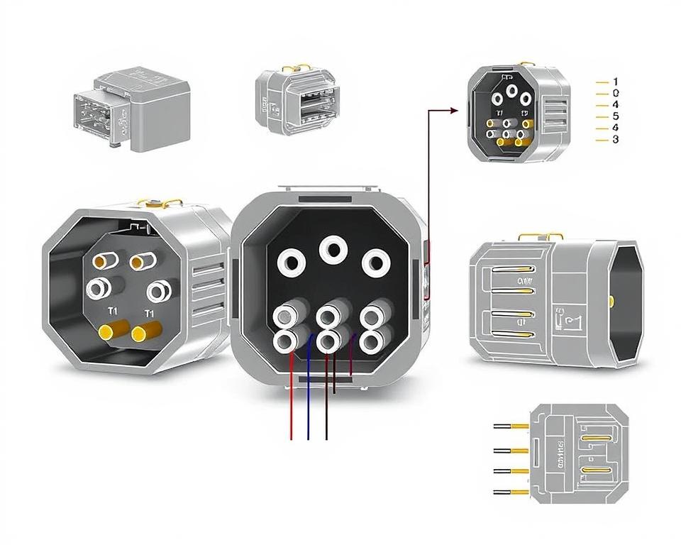
Comprehending NEMA Connector Configuration
Understanding of NEMA connector layout is crucial for forming proper connections in electrical systems. Knowledge about distinct pin configurations ensures security and appliance operation. There exists a range of NEMA couplers, intended for specific voltages and flows, covering:
| Connector Model | Ampere Rating | Voltage Rating |
|---|---|---|
| L5-15 | 15A | 125V |
| L5-20 | 20A | 125V |
| L14-20 | 20A | 125/250V |
| L1430C | 30A | 125/250V |
| L620C | 20A | 250V |
| L1430C | 30A | 125/250V |
| L630R | 30A | 250V |
Grasping NEMA coupler layouts is essential for secure junctions, improving effectiveness. It’s imperative to pair interfaces with appliances properly using rotary-lock or straight blade types, to dodge safety risks.
NEMA Device Wiring
NEMA device wiring covers multiple configurations for protected electrical appliance connections. These guidelines ensure that appliances integrate safely, lowering hazard. Understanding the different NEMA appliances and their wiring is vital for specialists.
Multiple Categories of NEMA Units
NEMA categorizes devices by category based on voltage levels and amperage demands. Essential setups are:
- 2-Pole, 2-Wire
- 2-Pole 3-Wire Grounding
- 3-Pole 3-Wire
- 3-Pole 4-Wire Grounding
- 4-Pole 4-Wire
- 4-Pole 5-Wire Grounding
These setups are employed in domestic settings and industrial facilities, supporting 125V, 208V, and 480V.
NEMA Outlet Wiring Demystified
NEMA plug wiring changes to suit various energy requirements, with locking types providing consistent connections in vibrating settings. For example, the L5-15 plug operates at 15 A, frequently used in business sites, whereas the L14-20 is crafted for 20 A at 125/250 voltage.
The NEMA naming scheme helps in picking the appropriate plugs, spotlighting attributes like polarity and earthing. This precision ensures that equipment perform reliably.
NEMA Receptacle Wiring Instructions
Accurate wiring of NEMA receptacles meets electrical regulations and security protocols. For instance, L530R receptacles are rated for 30 amps at 125 voltage, with L630R variants for 250 V. Correct grounding is essential to avoid electrical accidents.
Choosing accredited NEMA plugs and receptacles ensures safe, code-compliant setups. It’s imperative to refer to formal guidelines when implementing.
NEMA Motor Wiring and Implementations
NEMA motor wiring is essential in electrical design, especially for commercial use. Understanding how NEMA motor setup works ensures that machines are integrated for peak efficiency. Motors, like single-phase and three-phase variants, need accurate wiring to operate securely and effectively.
Overview of NEMA Motor Wiring
Understanding NEMA motor wiring requires knowledge of linkages and configurations. Nearly all three-phase motors offer dual-voltage, signifying they can operate at both low (208-230V) and high voltage levels (460V). Wiring at high voltage allows motors to draw less current than at low voltage. The benefits of high voltage include thinner cables for the supply, a notable benefit for units over 10 HP.
While both NEMA and IEC units are utilized in the market, NEMA models are typically bigger and more costly than IEC ones for below 100 HP applications. NEMA controllers span size 00 to 9, fit for diverse uses. A typical attribute in NEMA controllers is a Trip Rating of 20, designed to trip when a motor’s draw surpasses six times the Full Load Amperage (FLA) in 10 secs.
Choosing the Right NEMA Motor Setup
Choosing the correct NEMA motor arrangement influences overall performance and safety. A common three-wire control circuit uses three wires for a on/off pushbutton panel, allowing simple motor operation. Frequent three-phase configurations consist of the 12 Lead Dual Voltage and 6 Lead, enabling Wye and Delta arrangements.
IEC motor starters frequently incorporate phase loss detection, increasing safety. They also include adjustable Trip Ratings for tailored protection in low voltage operations. Furthermore, many models have heat protection, vital for one-phase and Dual Voltage setups.
| Configuration Type | Voltage Type | Current Rating | Usual Function |
|---|---|---|---|
| 12 Lead Dual Voltage | Dual Voltage (208-230V / 460V) | Varies by motor size | Applications with Wye Start and Delta Run |
| 6 Lead | Single or Dual Voltage | Up to 32 amps | Wye/Delta configurations |
| Single Phase | Single-level Voltage | Varies (1-5 amps adjustment) | Applications with Two Speed, Two Winding |
| Delta Connection | Elevated Voltage | Depending on setup | Various applications including Current Transformers |
Bringing It All Together
Comprehending NEMA wiring schematics and norms is vital for electrical specialists aiming to enhance their expertise and adhere to electrical safety standards. These guidelines guarantee protected and high-performing electrical installations but also avert hazards linked to incorrect wiring. In summary, complying with NEMA standards leads to the augmented functionality of multiple NEMA appliances and setups.
For technicians, the selection of quality materials can significantly impact the result of their work. Installation Parts Supply presents a wide range of wiring items aligned with NEMA norms. This enables professionals to obtain vital components for meeting these key regulations. High-quality supplies and comprehensive understanding of NEMA wiring schematics substantially improve project protection and efficiency.
Throughout electrical deployments, always place safety and exactness first. Mastering NEMA criteria delivers the insight necessary for applying best practices accurately. This ensures that each electrical junction made aligns with premium standards.
FAQ
Which are NEMA wiring diagrams?
NEMA wiring drawings display the setups and connections of NEMA-standard electrical gadgets. They comply with safety and operational standards defined by the National Electrical Manufacturers Association.
What makes NEMA criteria crucial for electrical security?
NEMA criteria are essential to establishing safety and operational criteria for electrical equipment. These guidelines help electrical specialists reduce electric shock, operational errors, and fire hazards.
What components are crucial in a NEMA wiring drawing?
Key elements in a NEMA wiring schematic include circuit setups and linkage diagrams. These schematics also offer thorough labels and show the electrical system’s different parts correctly for setups.
What types of NEMA wiring drawings exist?
Multiple NEMA wiring drawings cater to different requirements, including power distribution circuits and component interconnection schematics. Every layout serves a unique role in electrical setups.
Which are the typical symbols found in NEMA wiring diagrams?
Standard symbols in these diagrams symbolize switches, circuit breakers, outlets, and additional components. Utilization of these symbols facilitates effective conveyance and precise understanding of wiring drawings.
Which are the essential attributes of accurate electrical wiring drawings?
Accuracy in electrical wiring drawings is characterized by their lucidity, completeness, and detailed annotation. They should conform to NEMA criteria to avoid errors in deployment.
What is a NEMA connector pinout?
A NEMA connector configuration outlines electrical connections at a connector, showing distinct pin assignments. This ensures reliable and optimal linkages in electrical systems.
What are the different types of NEMA appliances?
NEMA units include various electrical sockets and couplers, like connectors and receptacles. They are designed for different amperage and power criteria to meet specific usage needs.
In what way is NEMA plug wiring arranged?
NEMA plug wiring depends on defined current and voltage levels needs, adhering to safety standards and code compliance for diverse electrical applications.
Identify the recommendations are there for NEMA receptacle wiring?
Standards for connecting NEMA sockets stress adhering to electrical standards, ensuring proper charge alignment, and picking correct wire sizes. This maintains both protection and functionality in electrical installations.
What is the method to wire a NEMA motor effectively?
To connect a NEMA motor, one must comprehend its specific one-phase or three-phase configuration. Choosing the appropriate wiring method is crucial, plus maintaining electrical safety for enhanced motor functionality.
What must be taken into account when selecting a NEMA motor arrangement?
Opting for a NEMA motor arrangement demands an evaluation of the project’s power needs and functional attributes. It’s also vital to confirm alignment with current machinery for assured performance and safety.